Add chamfers and reveals
Bevel panel and opening edges with chamfers, and lay out reveal (rustication) strips — singly or as a full grid.
A chamfer is a beveled edge cast into the concrete — around the panel perimeter and around openings — so exposed corners are broken rather than left sharp. A reveal (also called a rustication) is a shallow architectural groove formed into a panel face; placed horizontally and vertically, reveals produce the score lines and grids seen on tilt-up exteriors. Each has its own dialog, and both are drawn, dimensioned, and counted automatically when the panel redraws.
Steps
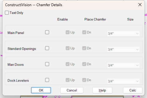
The Chamfer Details dialog, shown with the sample building’s data.
Chamfer panel and opening edges
Open Chamfer from the toolbar, or check Chamfer in the Main Panel Details feature checklist — either route opens the Chamfer Details dialog.
Check Enable on each group of edges you want chamfered: Main Panel, Standard Openings, Man Doors, Dock Levelers. Each group is configured independently.
On each enabled row, check Up, Dn, or both — the panel face(s) whose edges receive the chamfer.
Pick a Size: 1/2”, 3/4”, or 1”.
Confirm with OK. The feature switches on automatically and the panel redraws with the chamfered edges cut. With Text Only checked, the cut is skipped and a note — for example 3/4” Chamfer Up on: Panel Edges — is placed instead.

The Reveal Details dialog, shown with the sample building’s data.
Add a reveal
Open Reveals from the toolbar, or check Reveal in the Main Panel Details feature checklist — either opens the Reveal Details dialog.
The dialog holds up to 48 strips, eight rows per page. Use the page buttons (1-8 through 41-48) to reach more rows.
Check Enable on a free row. The row’s fields light up.
Choose the orientation — H (horizontal) or V (vertical). Fields that don’t apply to the chosen orientation grey out.
Set the position and size fields (see the table below), or use the Snap To checkboxes to register a strip end against a panel edge.
Choose the face — U (up — the inside of the building), D (down — the outside), or both.
Add more rows as needed, then confirm with OK. The panel redraws with every enabled reveal formed into the face and dimensioned.
Build a reveal grid
Spacing is explicit — every strip is its own row, so there is no repeat field to fill in. To lay out a grid:
Enable one H row per horizontal score line, setting each row’s elevation to that line’s height.
Enable one V row per vertical score line, setting each row’s Distance to that line’s position across the panel.
Give every row the same Strip Width and Thickness — crossing strips of equal thickness merge into a clean intersection with no demarcation lines.
With 48 rows available, a full-facade grid fits comfortably in one panel.
Chamfer Details fields
Field |
What it does |
|---|---|
Enable |
Turns chamfering on or off for that group of edges (Main Panel, Standard Openings, Man Doors, Dock Levelers). |
Up / Dn |
Which panel face’s edges are chamfered — up (near) face, down (far) face, or both. |
Size |
The chamfer size: 1/2”, 3/4”, or 1”. Each group can use a different size. |
Text Only |
Places the chamfer notes without cutting the edge geometry, and greys the Up/Dn boxes. Use it if chamfering a complex panel is slow or fails — the drawing still calls out the chamfer. |
Reveal Details fields
Field |
What it does |
|---|---|
Enable |
Turns the row on or off. An unchecked row keeps its values but is not drawn — handy for template panels and design changes. |
Horiz/Vert (H / V) |
The strip’s orientation on the panel face. |
Snap To (L / R / T / B) |
Registers a strip end flush against the chosen panel edge. A horizontal strip snaps L/R; a vertical strip snaps T/B. A snapped strip cannot be arched. |
Measure From (L / R) |
Which side of the panel the Distance is measured from; the dimension is drawn from that side. |
Distance |
Distance from the chosen panel side to the strip — to the near end of a horizontal strip, or to a vertical strip’s position across the panel. 0 places it at the panel edge. |
Elev Left / Elev Right |
Elevation of the top of a horizontal strip above finished floor, at each end. Enter different values to slope the strip. A vertical strip uses only Elev Left for its starting height. |
Length |
Overall length of the strip. 0 extends it to the panel edge. |
Arch Radius |
Curves a horizontal strip. Positive values arch upward, negative downward; a radius smaller than half the length draws a full circle centered at the Distance and Elevation. When a radius is set, Elev Right follows the arc. |
Strip Width |
Width of the reveal strip material. |
Thickness |
Depth of the strip — picked from the project’s material-thickness list. |
On Face (U / D) |
Which panel face carries the strip: up (inside the building), down (outside), or both. |
Panel Edge (L / R) |
Carries the strip onto the selected side edge of the panel, following mitered sides. |
I (Inside openings) |
Also places the strip on the inside edges of openings it crosses. |
N (No dim) |
Suppresses dimensioning for this strip — useful inside dense grids. |
Notes
Reveals draw on the panel face and are trimmed from intersecting openings. Up-face reveals are carried around the surfaces of intersecting pilasters and lintels. Reveals are not trimmed from ledgers, weld connections, or pick and brace points.
Each strip is dimensioned to its ends (unless an end is coincident with the panel side), with an elevation marker at the top edge of the strip’s end — both ends when the strip is sloped. Text near the panel edges notes where a strip extends onto the panel sides or into openings.
A reveal is referenced to the face it sits on — a down-face strip measures from the down (outside) face, an up-face strip from the up (inside) face — regardless of the panel’s distances-from setting.
Ledgers and top plates that cross a chamfered edge are not trimmed to the chamfer.
The materials list counts chamfer strip by chamfer size and reveal strip material by strip size, so the take-off follows what you draw — see Generate a materials list.
To print the panel with the reveal layer set preset, use CV → Print → Panel → Reveal — see Plot and print drawings.