Add a ledger and top plate
Place a ledger bar or a top plate on a panel, with its cast-in anchor bolts.
A ledger is a section of treated lumber (or metal) running across the inside face of the panel, attached with anchor bolts cast into the wall — used to carry floor and roof systems. A top plate (nailer strip) is the same idea placed along the top of the panel, and it normally also forms the panel’s top edge form. Both are defined in the same dialog, one row per bar; the anchor bolts draw automatically with each bar.
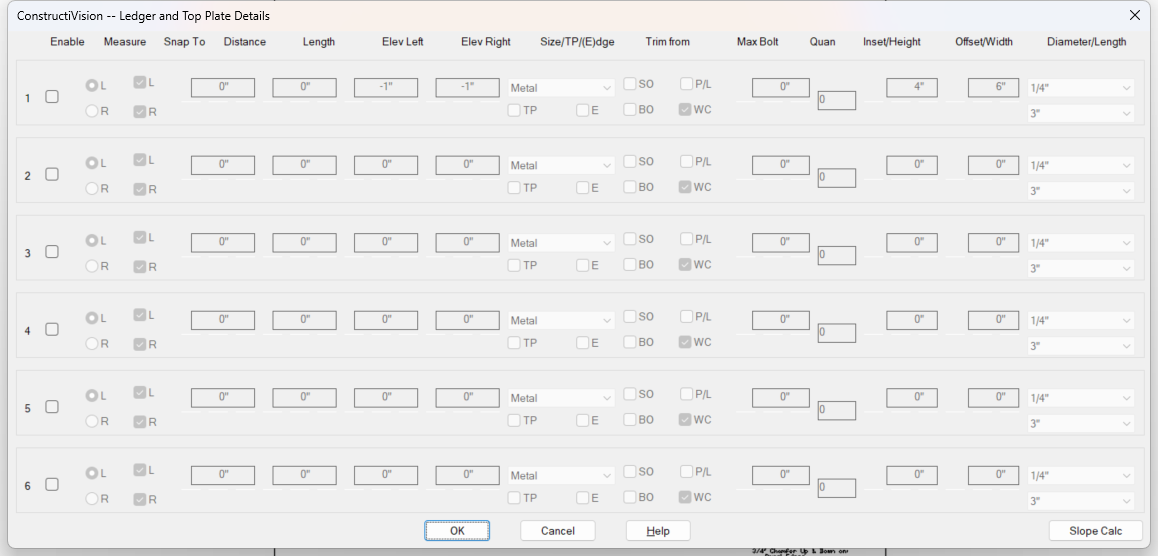
The Ledger and Top Plate Details dialog, shown with the sample building’s data.
Steps
Open Ledger / Top Plate for the panel — from the toolbar, or from the Main Panel Details feature checklist.
Enable a row. Its fields activate. The dialog holds six rows; each row is one ledger, or one top plate if its TP toggle is checked.
Set the row’s values:
Field
What it sets
Enable
Draws this bar. A disabled row keeps its values without drawing — useful for staging bars in a template panel.
Measure From (L / R)
Which side of the panel the Distance is measured from. The baseline dimension is drawn from that edge to the near end of the bar.
Snap To (L / R)
Registers an end of the bar against a panel edge. Snapping the end on the Measure From side zeroes and greys Distance; snapping the opposite end zeroes and greys Length (the bar runs to that edge); snapping both spans the full panel width.
Distance
From the chosen panel side to the near end of the bar. 0 starts the bar at the edge.
Length
Overall length of the bar. 0 extends it to the far panel edge.
Elev Left / Elev Right
Elevation of the top of the ledger, above the finished floor, at each end — enter different values for a sloped ledger. Greyed out when TP is checked.
Size
Metal, or the nominal lumber size — 2 X 4 up through 6 X 14. Lumber draws at its actual (dressed) size, 1/2” under nominal.
TP
Makes the row a top plate: the bar snaps to the top of the panel, so the elevation fields do not apply.
E
Stands the bar on edge — narrow side against the concrete instead of the wide side.
Trim from (SO / BO / P/L / WC)
Whether the bar is trimmed where it crosses Standard Openings, Blockouts, Pilasters / Lintels, or Weld Connections. See the notes below for what each choice does.
Max Bolt
Maximum center-to-center bolt spacing. The actual spacing is adjusted to space the bolts evenly along each segment.
Quan
A specific bolt count instead of spacing-driven placement; the spacing adjusts automatically. Which of Max Bolt and Quan is active depends on the P/L trim choice: with P/L trim on, the row is quantity-driven (Quan active); otherwise it is spacing-driven (Max Bolt and Inset active).
Inset
Inset of the first and last bolt from the ends of the bar. May be adjusted to center the bolt array in a segment.
Offset
Offset of the bolts from the bar’s centerline. 0 places them on center; enter D for a double row of bolts (warns if a double row will not fit the bar’s size and orientation).
Diameter / Length
The anchor-bolt size: diameter from 1/4” to 2”, length from 3” to 24”. Bolts too short to reach through the bar into the concrete, or too long to keep 1” of cover, are warned about.
Add more rows if needed — each bar is configured independently. The Slope Calc button opens the Slope Calculator if you need to work out sloped-ledger elevations.
Confirm. The feature’s master toggle turns on automatically once at least one row is enabled.
Redraw the panel. Each bar is drawn on the panel face with its anchor bolts, a callout above it (size, orientation, and bolt size / spacing — e.g. 4 X 6 Top Plate on Edge - 3/4 X 5 1/2 AB @ 3’-0” o.c. Max), and elevation markers to the top of the bar.
Notes
The anchor bolts draw on their own hardware layer, so they can be shown or printed separately. A minimum of two bolts per segment is maintained even where that overrides the spacing and inset you entered.
Trim behavior. With a trim toggle checked, the bar is cut where it crosses that feature — ledgers are trimmed out, and top plates step down into standard openings (top plates trimmed from blockouts are removed entirely). With the toggle unchecked, the bar is left whole but the intersecting bolts are removed — except at weld connections, where nothing is removed.
Pilasters and lintels are a special case: unchecking P/L trim segments the ledger and places it on the pilaster’s or lintel’s top surface instead of cutting it. Top plates are not affected by the P/L choice.
Man doors and dock levelers always trim the ledger (and step bolts into the remaining segments) unless the opening is marked as a future opening.
Bars are mitered with the panel sides at inward-facing corners only, and are not trimmed to follow chamfered edges.
The Materials List counts the lumber and the bolts for each bar, segregated by size — see Generate a materials list.
To print the panel showing just this feature, use the Ledgers / Top Plate layer preset on the CV → Print → Panel menu — see Plot and print drawings.