Tutorial 2: Panel Options
Master the Main Panel Details dialog — dimensions, elevations, a peaked top, casting face, expansion gaps, and the Panel Features checklist — by building a real panel.
Main Panel Details is the panel’s home form: every panel starts here, and every other feature dialog hangs off it. In this lesson you set each group on the form with real values and end with a dimensioned, peaked tilt-up panel you can check against the numbers you typed.
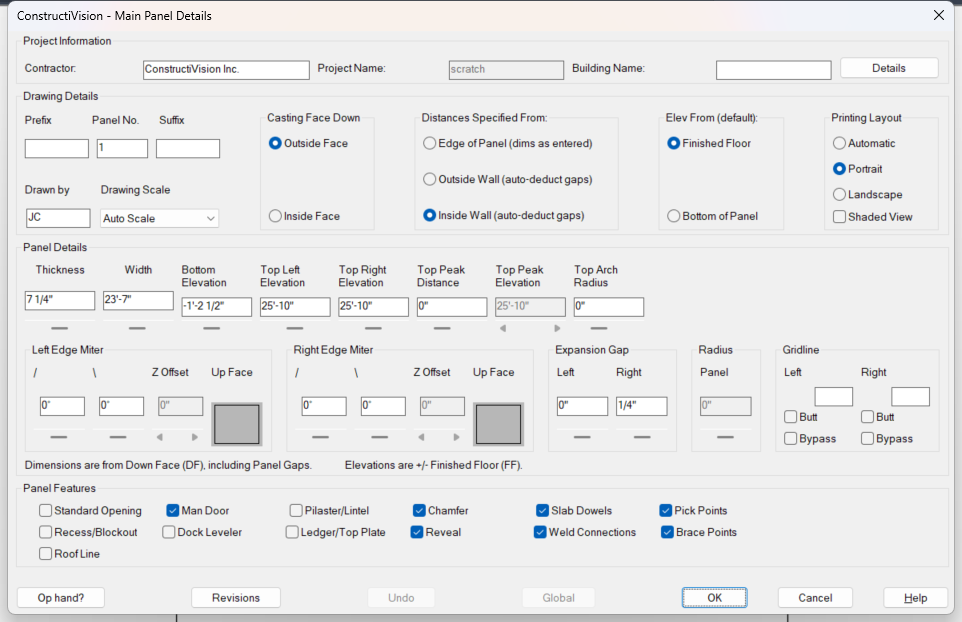
The Main Panel Details dialog — Drawing Details, Panel Details, and the Panel Features checklist.
Note
A browser version covers part of this lesson. Open it here — it lists exactly which steps it does not cover, so you know what to come back to AutoCAD for.
Watch this lesson
Transcript (16 captions)
0:01 — Tutorial 2 — Panel Options. Panel TP08-12: 25'-10" wide, 7 1/4" thick, gable top.
0:06 — Open Main Panel Details — Edit Main Panel, or New Drawing → Panel.
0:08 — Drawing Details — the mark. Prefix TP08-.
0:12 — Panel No. 12 — digits only; letters belong in prefix or suffix.
0:16 — Add your initials under Drawn by. Leave Drawing Scale on Auto.
0:21 — Casting Face Down stays Outside Face — cast as it lies on the slab.
0:26 — Panel Details. Thickness 7 1/4 — type exact values; the slider roughs in.
0:31 — Width 25'10 — 25'10, 25'-10", or 310 all mean the same thing.
0:35 — Elevations measure from Finished Floor. Bottom: -1'6 — below FF.
0:39 — Top Left 22'1 — watch it copy into Top Right: a flat top is one entry.
0:46 — Top Peak Distance 12'11 from the left edge — half of 25'-10", a centered peak.
0:50 — Top Peak Elevation 24'6 — the gable peak above Finished Floor.
0:55 — The Panel Features checklist — twelve toggles, one per feature. A checked box always means the panel really carries that feature. Later lessons fill these in.
1:04 — OK — ConstructiVision draws the dimensioned panel.
1:16 — Gable outline, mark bubble TP08-12, elevation callouts, dashed FF line.
1:21 — Check your work: type CV-CHECK-LESSON2 at the command line for a graded report card.
Tip
The written steps below are the authoritative version — they are kept current continuously, while videos are re-recorded in batches. Companion video versions lists which build each video was recorded against.
Recorded in the earlier lesson order
This video was recorded before the course moved to build order (2026-10-09). It does not show step 8, the expansion gaps, which used to come at the end of Tutorial 9; that lesson’s video shows them being entered.
What you will build
Panel TP08-12: a 25’-10” wide, 7 1/4” thick panel with its bottom 1’-6” below Finished Floor, eaves at 22’-1” on both sides, and a center roof peak at 24’-6” — a classic gable-end panel — with a 1/2” expansion gap at each edge, so you type the 25’-10” plan width and the panel casts at 25’-9”. When you finish, the drawing shows the dimensioned outline, the elevation callouts, the Finished Floor line, and the mark bubble, all matching the values in this lesson.
Before you start
Complete Tutorial 1: Getting Started with ConstructiVision — you need ConstructiVision loaded and a project open. Tutorial 10: Site Drawing comes between them in the course: its wall lines already list TP08-12, the panel this lesson builds, but nothing here depends on the site.
The general onboarding walkthrough in Getting Started covers the same ground in less depth if you want a refresher first.
Lesson
Open Main Panel Details. Click New Drawing and choose a Panel drawing. The Main Panel Details dialog opens on the new panel. (For an existing panel you would reach the same dialog with Edit Main Panel.)
Give the panel its mark. In Drawing Details, enter:
Prefix:
TP08-Panel No.:
12(1–4 digits, digits only — letters belong in the prefix or suffix)Suffix: leave empty
The mark TP08-12 is what the panel is called everywhere — the mark bubble on the sheet, the revision history, and the file name. Add your initials under Drawn by, and leave Drawing Scale on Auto Scale for now.
Choose the casting face. Leave Casting Face Down on Outside Face — the panel is drawn as it lies on the slab during construction, and most panels are cast outside face down. You would pick Inside Face only for finishes like exposed aggregate that need the outside wall facing up in the casting bed.
Set thickness and width. In Panel Details, every value has an edit box with a slider under it — type exact values in the box, or drag the slider to rough something in. Enter:
Thickness:
7 1/4Width:
25'10
Tip
Enter dimensions in whatever format you read them off the plans:
25'10,25'-10", or310all mean the same thing. A value without a foot mark (') is read as inches. Fractions ride along after a hyphen or a space —12'11-3/4and12'-11 3/4"both read correctly. The boxes read dimensions, not math: an expression like12'11 + 3/4is rejected as an invalid entry.Set the elevations. Panel height comes from elevations, not a height field — every elevation on this dialog is measured from Finished Floor (FF), positive above and negative below (the note at the bottom of the dialog says exactly this). Enter:
Bottom Elevation:
-1'6— the panel bottom sits 1’-6” below Finished Floor.Top Left Elevation:
22'1— enter the left value first: it is automatically copied into Top Right Elevation, so a flat-top panel is one entry. Leave Top Right at the copied 22’-1”.
Bottom to top: 1’-6” + 22’-1” = a 23’-7” tall panel at the eaves.
Add the roof peak. The two peak fields turn the flat top into a gable:
Top Peak Distance:
12'11— where the peak sits, measured from the left edge of the panel. 12’-11” is half of 25’-10”, so this peak is centered. A distance of0means no peak — which is why the Top Peak Elevation box is grayed out while the distance is zero: enter the distance first.Top Peak Elevation:
24'6— the height of the peak above Finished Floor.
(The neighboring Top Arch Radius field is the curved-top alternative — entering a radius replaces the peak and right-elevation entries. Leave it at
0for this panel.)Set the Elev From default. The Elev From (default) choice sets which datum the feature dialogs — openings, connections, pick points — use to display their elevations: Finished Floor or Bottom of Panel. It is a display lens, not a data change: switching it re-expresses the same stored elevations from the other datum, and individual feature dialogs can switch their own lens when you get to them. Leave it on Finished Floor, the convention architectural plans use.
Set the expansion gaps. Find the Expansion Gap box — next to the Edge Miter groups — with its Left and Right entries, and above it the Distances Specified From: choice. The two work as a pair:
Edge of Panel (dims as entered) — dimensions are taken exactly as typed, so they must already include any gap allowances. With this choice the Expansion Gap values are ignored when the panel is drawn.
Outside Wall / Inside Wall (auto-deduct gaps) — dimensions are read as the architectural call-outs to the wall line, and ConstructiVision deducts the expansion gaps automatically when the panel is drawn.
Select Outside Wall (auto-deduct gaps), then type Left
1/2and Right1/2. A value without a foot mark is inches, so that is half an inch per edge — a typical panel joint gap. This is what makes typing the plan width in step 4 legitimate: the panel casts at 25’-9”, and in every later lesson you keep typing plan dimensions while ConstructiVision draws them from the cast edges. Without the gaps, the width field must carry the exact casting width, and every gap allowance is yours to figure by hand.Tour the Panel Features checklist. The toggles at the bottom are the panel’s feature inventory, in the order the work is done in the field: Standard Opening, Man Door, Dock Leveler, Recess/Blockout, Pilaster/Lintel, Chamfer, Feature Strip, Weld Connections, Slab Dowels, Ledger/Top Plate, Roof Line, Pick Points, Brace Points (openings first, then recesses, the face, connections and edges, and lifting and bracing last). Checking a toggle opens that feature’s dialog so you can define it on the spot — the same dialogs the toolbar buttons open directly, and the toolbar follows the same order.
Try it: check Standard Opening, look around the dialog that opens, then leave it without enabling an opening. The toggle clears itself — a checked toggle always means the panel really carries at least one enabled row of that feature, so the checklist doubles as an honest at-a- glance summary of what is on the panel. Leave all thirteen unchecked for now; the next lessons fill them in one at a time.
Confirm. Click OK. ConstructiVision draws the dimensioned panel.
Check your result
Tip
Check your work automatically. Type CV-CHECK-LESSON2 at the command line —
ConstructiVision grades your panel against this lesson’s values and prints a report card, with a
pointer back to the step for anything that doesn’t match.
The drawing should now show, matching your entries exactly:
The panel outline with a gable top — eaves at both sides and a peak in the middle — and its overall width dimension reading 25’-9”: the 25’-10” you typed, less the two 1/2” gaps.
The mark bubble reading TP08-12.
Elevation callouts: bottom at -1’-6”, top left and top right at 22’-1”, and the peak at 24’-6”, centered.
A dashed red Finished Floor line across the panel — drawn because the panel bottom is below FF.
Main Panel Details, reopened, holding
1/2in both Expansion Gap boxes, Distances Specified From on Outside Wall, and the width still reading the 25’-10” you typed.
If a value came out wrong, open Edit Main Panel, fix the field, and confirm — the panel redraws from the corrected values. That dialog → confirm → redraw loop is the whole product in miniature.
Going deeper
One group on this dialog was left at its defaults and has its own reference depth: the Gridline group (site grid bubbles beside the panel — see Set panel marks and gridline marks). The Edge Miter boxes are covered with the other edge treatments in Add chamfers and reveals.
Where next
Next lesson: Tutorial 6: Standard Opening — cut the panel’s window openings, the first of the cuts through the full depth.
Reference depth: Set panel marks and gridline marks for everything the mark and gridline fields can do, and Command & Toolbar Reference for where every feature dialog lives.