Tutorial 3: Panel Lines
Draw the panel’s reference lines — sloped roof lines across the face — and control each segment’s run and elevation.
Panel lines are the dashed reference lines you add across a panel’s face. In ConstructiVision they are drawn with the Roof Line tool: each line is a segment with its own start, length, and an elevation at each end, so one flat line, a single slope, or a full compound roof profile are all the same three or four entries per row. The lines are reference geometry only — they change no concrete and add nothing to the materials list — but other features can measure to them: the Roofline option in Weld Connection Details makes a whole connection array track the line you draw here.
Note
This lesson also exists in the browser. Work it in ConstructiVision on the web — same steps, same values, so you can follow either and end up with the same panel.
Watch this lesson
Transcript (21 captions)
0:01 — Tutorial 3 — Panel Lines. Panel TP08-12 from Tutorial 2: a two-segment roof line, parallel to the gable top and 2'-0" below it.
0:09 — Click Roof Line on the ConstructiVision toolbar — panel lines live only behind this button.
0:11 — Six rows, one per segment: Enable, Meas From, Snap To, then Distance, Length, Elev Left, Elev Right. Length 0 runs to the panel edge.
0:19 — Row 1 — the left slope. Check Enable; the row lights up.
0:21 — Meas From L — measurements taken from the panel's left edge.
0:23 — Clear Snap To R first — L and R are independent, and snapping both ends would leave nothing to measure.
0:25 — Snap To L — the segment starts flush at the left edge. Distance sets itself to 0" and greys out.
0:27 — Length 12'11 — the segment runs to the centerline, directly below the peak.
0:31 — Elev Left 20'1 — 2'-0" below the 22'-1" eave.
0:35 — Elev Right 22'6 — 2'-0" below the 24'-6" peak. Two different end elevations make the segment sloped.
0:39 — Row 2 — the right slope, the mirror image. Check Enable.
0:41 — Meas From L again.
0:43 — Clear Snap To L on this row — row 2 ends at the right edge only.
0:45 — Snap To R — the segment runs to the right edge, so Length takes care of itself and greys out.
0:47 — Distance 12'11 — row 2 starts where row 1 ended, at the centerline. Keep segments contiguous.
0:51 — Elev Left 22'6 — matching row 1's right end, so the segments meet at the peak.
0:55 — Elev Right 20'1 — back down to 2'-0" below the right eave.
1:00 — Elev From — Finished Floor, Bottom of Panel, Top of Panel — is a display lens only. Leave it on Finished Floor, how these values are written.
1:09 — OK — the panel redraws with the roof line on it.
1:21 — Two dashed red segments meeting 12'-11" from the left edge — 20'-1" up to 22'-6" and back down — with Roof Line elevation markers. The concrete is untouched.
1:37 — Check your work: type CV-CHECK-LESSON3 at the command line for a graded report card.
Tip
The written steps below are the authoritative version — they are kept current continuously, while videos are re-recorded in batches. Companion video versions lists which build each video was recorded against.
Recorded in the earlier lesson order
This video was recorded before the course moved to build order (2026-10-09). It opens on the bare panel from Tutorial 2. In build order the panel already carries the windows, door, chamfer, weld connections, ledger and top plate from Tutorials 6, 5, 4, 7 and 8; the roof line goes on the same way.
What you will build
A two-segment sloped roof line on panel TP08-12 — the gable-end panel you have built since Tutorial 2 (25’-10” plan width, eaves at 22’-1”, peak at 24’-6” set 12’-11” from the left edge), now carrying its openings, chamfer, embeds, ledger and top plate. You will draw the roof bearing line parallel to the panel’s top and exactly 2’-0” below it: rising from 20’-1” at the left edge to 22’-6” at the center, then falling back to 20’-1” at the right edge. When you finish, the panel shows both dashed line segments meeting at the center, with an elevation marker at each roof-line elevation.
Before you start
Complete Tutorial 8: Ledger & Top Plate — this lesson continues on the TP08-12 panel, and assumes you can open a panel drawing and use the dialog entry formats from Tutorial 2 (
22'6,22'-6", and270all mean the same thing).
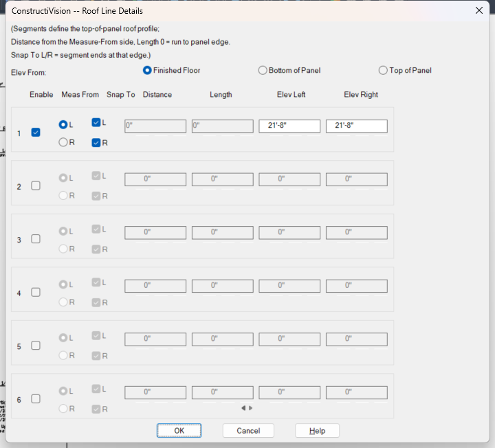
The Roof Line Details dialog — six segment rows and the Elev From datum choice.
Lesson
Open the panel. Open the TP08-12 panel drawing (use Open Drawing if it is not already on screen).
Open Roof Line. Click Roof Line on the ConstructiVision toolbar (if the toolbar is not visible, choose CV → Show CV Toolbar). The Roof Line Details dialog opens. Unlike the features on the Main Panel Details checklist, panel lines live only behind this button — which is why they get their own lesson.
The dialog holds six rows — one per line segment. Each row has an Enable toggle, Meas From and Snap To choices, and four measurements: Distance, Length, Elev Left, and Elev Right. As the note at the top of the dialog says, the segments define the top-of-panel roof profile: Distance is measured from the Measure-From side, a Length of 0 runs the segment to the panel edge, and Snap To L/R ends the segment at that edge.
Draw the left slope (row 1). Check Enable on row 1 and enter:
Meas From:
L— measurements for this row are taken from the panel’s left edge.Snap To: check
L— the segment starts flush at the left edge. Because the snapped edge is also the Measure-From edge, Distance sets itself to 0” and greys out — there is nothing left to measure.Length:
12'11— the segment runs to the panel’s centerline, directly below the peak.Elev Left:
20'1— the line’s height at the left edge: 2’-0” below the 22’-1” eave.Elev Right:
22'6— its height at the center: 2’-0” below the 24’-6” peak.
Two different end elevations make the segment sloped. (On a flat roof you would enter only Elev Left — an enabled row with Elev Right left blank draws a level line at the Elev Left height.)
Draw the right slope (row 2). Check Enable on row 2 and enter the mirror image:
Meas From:
LDistance:
12'11— the segment starts where row 1 ended, at the centerline.Snap To: check
R— the segment runs to the right edge. Snapping the edge opposite the Measure-From side means the length takes care of itself, so Length sets itself to 0” and greys out.Elev Left:
22'6— matching row 1’s right end, so the two segments meet at the peak.Elev Right:
20'1— back down to 2’-0” below the right eave.
Keep segments contiguous like this — each one starting where the previous one ends — so every point across the panel has a single, unambiguous roof-line elevation for the features that will measure to it.
Note the Elev From choice. The Elev From row at the top — Finished Floor, Bottom of Panel, Top of Panel — is the same display lens you met on the elevation fields in Tutorial 2: switching it re-expresses the elevations already in the boxes from the other datum, without changing what is stored. Leave it on Finished Floor, which is how this lesson’s values are written.
Confirm. Click OK. The panel redraws with the roof line on it.
Check your result
Tip
Check your work automatically. Type CV-CHECK-LESSON3 at the command line —
ConstructiVision grades your panel against this lesson’s values and prints a report card, with a
pointer back to the step for anything that doesn’t match.
The panel face should now show, matching your entries exactly:
Two dashed red line segments spanning the full panel width — from the left edge up to the center, and from the center back down to the right edge — meeting at the 12’-11” you entered, directly under the peak.
The line runs parallel to the panel’s gable top, 2’-0” below it for its entire length: 20’-1” at the left edge, 22’-6” at the center, 20’-1” at the right edge.
An elevation marker reading “Roof Line” at each roof-line elevation; for a compound slope like this one, the distance to the vertex is dimensioned as well.
The concrete is untouched — the outline, the openings and every feature from the earlier lessons are exactly as you left them. Panel lines annotate the panel; they never cut it.
Note
Why the drawn distances read 1/2” short. Tutorial 2 set a 1/2” expansion gap on each edge, with Distances Specified From on Outside Wall, so the panel casts at 25’-9” and a distance measured to a panel edge is drawn from the cast edge: 1/2” less than the plan value you typed. The dialogs keep the plan values exactly as you entered them.
To change the profile later, open Roof Line again — the rows come back with your values, in whichever Elev From datum you last used. Unchecking a row’s Enable keeps its values but removes the line from the drawing, which is handy on template panels.
Where next
Next lesson: Tutorial 9: Brace Points & Expansion Gaps — the last step on the panel: brace points.
Reference depth: the payoff for this lesson is in Add weld connections — the Roofline option makes a whole connection array follow the line you just drew, each plate’s elevation computed where it crosses the roof line. Command & Toolbar Reference lists where every panel tool lives.