Tutorial 7: Weld Connections
Add a joist embed type to the project catalog, then place panel-to-panel plates and a five-embed joist array on your panel — placed, dimensioned, and marked in one redraw.
Weld connections are steel embeds cast into the panel — the attachment points for joists, ledgers, canopies, and panel-to-panel joints after lifting. ConstructiVision draws each one as a simple box showing its size, location, and type mark; the fabricator’s detail drawings cover the rest. This lesson adds two things the earlier features did not have: a project-wide catalog (connection types are defined once per project, then every panel picks from the list) and an array (one row that places a whole run of evenly spaced embeds).
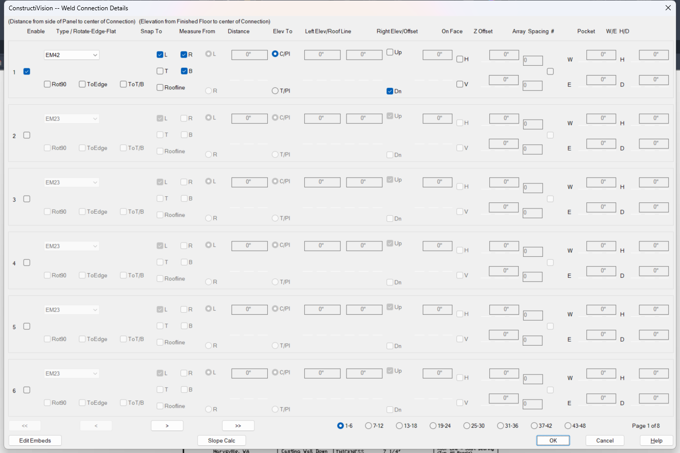
The Weld Connection Details dialog — one connection per row, six rows per page.
Note
This lesson also exists in the browser. Work it in ConstructiVision on the web — same steps, same values, so you can follow either and end up with the same panel.
Watch this lesson
Transcript (30 captions)
0:01 — Tutorial 7 — Weld Connections: the steel embeds cast into the panel. A joist embed type added to the project catalog, a panel-to-panel pair, and a five-embed array — placed, dimensioned, and marked in one redraw.
0:13 — Click Weld Connections on the toolbar — or check it in Main Panel Details. Either route opens the same dialog.
0:16 — One connection per row: Enable, Type with its orientation toggles, Snap To, Measure From, Distance, Elev To, the two elevations, On Face, Z Offset, Array with Spacing and count, and Pocket. The note on top gives the two conventions — Distance and Elevation both read to the CENTER of the connection. The buttons below page through all 48.
0:35 — The Type lists are stocked from the project's embed catalog — but our joist embed isn't in it yet. Edit Embeds opens the catalog.
0:37 — The Weld Connection Specifications table — the PROJECT'S catalog: define a type once, every panel can place it. No Add or Delete buttons: type into an empty row to add, blank a Type cell to delete. And heed the hint — the Type mark prints on the panel at every embed, so keep it short.
0:56 — Jump to the last page — the table always keeps spare blank rows after the catalog.
0:57 — On an empty row: Type EM6 —
1:01 — — Width 6 —
1:05 — — Height 6 —
1:09 — — Thickness 1/4.
1:13 — A description for the humans. The two ID columns are optional — leave them blank.
1:19 — OK — EM6 joins the catalog, and every row's Type list on every panel in the project now offers it.
1:21 — Row 1 — the panel-to-panel pair. Check Enable; the row wakes up.
1:23 — Type: the starter catalog's 9 x 4 plate marked A.
1:27 — Instead of a distance, Snap To: L —
1:28 — — and R at once: an identical connection flush to EACH side edge from a single row. Measure From and Distance grey out — derived.
1:29 — Elev To stays C/Pl — to the center of plate. Left Elev 18'0 above Finished Floor, well over the window heads.
1:34 — On Face stays unchecked and Z Offset 0 — the plate centers in the 7 1/4" thickness. The orientation toggles stay clear; the default is right for this joint.
1:36 — Row 2 — the joist array. Enable —
1:38 — — and Type EM6: the type you just defined.
1:41 — Measure From stays on L. This row is one embed plus the instruction to repeat it.
1:42 — Distance 2'11 — for a horizontal array, the distance to the FIRST plate.
1:46 — Left Elev 20'0 — below the 22'-1" eaves, clear of the roof structure. Watch Right Elev copy it — the run stays level; differing elevations would slope the array.
1:53 — On Face: Up — the embeds sit on the panel surface facing up in the casting bed, not centered in the thickness.
1:54 — Array: H —
1:56 — — Spacing 5'0 center to center —
2:00 — — and count 5. A count of 0 would auto-fill as many as fit; typing 5 makes the result exactly checkable.
2:04 — OK — Weld Connections switches on automatically and the panel redraws: all seven embeds in one pass.
2:16 — The A plates flush to each edge at 18'-0", and the five EM6 embeds at 20'-0": first one 2'-11" from the left, 5'-0" on center — the middle embed lands at 12'-11", directly under the roof peak, and the last mirrors the first, 2'-11" from the right. Each marked with its type, dimensioned, with elevation markers to center of plate.
2:33 — Check your work: type CV-CHECK-LESSON7 at the command line for a graded report card — the catalog entry, both rows, and the feature toggle.
Tip
The written steps below are the authoritative version — they are kept current continuously, while videos are re-recorded in batches. Companion video versions lists which build each video was recorded against.
Recorded in the earlier lesson order
This video was recorded before the course moved to build order (2026-10-09). The panel in it already carries the roof line from Tutorial 3, which now comes after Tutorial 8. Nothing in this lesson uses the roof line.
What you will build
You continue with panel TP08-12 — the gable-end panel with eaves at 22’-1”, a center peak at 24’-6”, the windows and door from Tutorials 6 and 5, and the chamfer from Tutorial 4. In this lesson you:
meet the starter catalog of embed types every new project is born with, and add one type of your own to it: a 6” × 6” joist embed marked EM6;
place the starter catalog’s 9” × 4” A plate flush to each side edge at 18’-0” above Finished Floor as a panel-to-panel pair — one dialog row;
place a horizontal array of five EM6 embeds at 20’-0”: the first 2’-11” from the left edge, then 5’-0” center to center — which lands the middle embed at 12’-11”, directly under the roof peak, and the last one 2’-11” from the right edge.
When you finish, all seven embeds are drawn at their real size, dimensioned, and marked with their type.
Before you start
Complete Tutorial 4: Chamfer — this lesson picks up the project and panel TP08-12 where that lesson left them.
Have panel TP08-12 open. Any panel works — the values below are what make the result checkable.
Lesson
Open Weld Connection Details. Click Weld Connections on the toolbar, or check Weld Connections in the Main Panel Details feature checklist — either route opens the same Weld Connection Details dialog.
Read the grid. Same row-per-feature pattern as Lesson 6, with more columns: Enable, Type (with three orientation toggles under it), Snap To (L / R / T / B, plus Roofline), Measure From (L / R), Distance, Elev To (C/Pl / T/Pl), Left Elev / Roof Line, Right Elev / Offset, On Face (Up / Dn), Z Offset, Array (H / V with Spacing and #), and Pocket. Six rows show at a time; the 1-6 / 7-12 / … / 43-48 buttons at the bottom page through all 48 connections a panel can carry. The note across the top of the dialog states the two measuring conventions:
Distance is from the side of the panel to the center of the connection.
Elevation is from Finished Floor to the center of the connection.
As in every lesson, a row’s fields stay greyed out until its Enable box is checked.
Look at the catalog, then add your own type. Check Enable on row 1 — its fields wake up — and open the Type drop-down: it is already stocked. Every new project is born with a starter catalog of common embed types — among them the 9” × 4” plate marked A you will place in the next step. The joist embed for this lesson is not in it, so click Edit Embeds at the bottom of the dialog. The Weld Connection Specifications table opens — this is the project’s embed catalog: 18 editable rows per page with columns ID, Type, Width, Height, Thickness, Structural ID, Fabricator ID, and Description. There are no Add/Delete buttons — type into an empty row to add a type, and blank out a Type cell to delete one. An Example line above the table shows the pattern a filled-in entry follows. Click >> to jump to the last page — the table always keeps spare blank rows after the catalog — and enter the joist embed on the first empty row:
Type:
EM6— Width:6— Height:6— Thickness:1/4Description:
Joist seat embed(the two ID columns are optional — leave them blank)
Confirm with OK. EM6 now appears in every row’s Type drop-down, alongside the starter types.
Note
The catalog is project-wide: type definitions live with the project, and only the type reference and placement are stored in each panel. Define a type once and every panel in the project can place it — and heed the hint printed in the editor: the Type mark is printed on the panel at each embed location, so keep it short or the drawing gets crowded.
Row 1 — the panel-to-panel pair. Row 1 is already enabled from the previous step. Pick Type A from the drop-down, then instead of typing a distance, use Snap To: check L and R at once. Snapping both edges places an identical connection flush to each side edge from a single row, and the Measure From and Distance fields grey out — they are now derived. Set the height of the pair:
Elev To: leave on C/Pl — elevations read to the center of the plate. (T/Pl is for plans that call out top-of-plate instead.)
Left Elev:
18'0— Finished Floor to plate center, well above the window heads.On Face: leave Up and Dn unchecked, and Z Offset at
0. With neither face checked, a zero Z offset centers the plate in the panel’s 7 1/4” thickness — exactly what you want for a plate lying flat on the panel edge.
Leave the Rot90 / ToEdge / ToT/B toggles under the Type unchecked — they rotate the plate 90°, face it toward the nearest edge, or face it toward the top/bottom, and the default orientation is right for this joint.
Row 2 — the joist array. Check Enable on row 2 and pick Type EM6. This row is one embed plus the instruction to repeat it:
Measure From: L
Distance:
2'11— for a horizontal array this is the distance to the first plate.Left Elev:
20'0— below the 22’-1” eaves, clear of the roof structure. The Right Elev field copies your entry automatically, so the run stays level — the same left-first convention as the top elevations in Lesson 2. (Differing left and right elevations slope the array; that is what the Right Elev column is for.)On Face: check Up — the embeds sit on the panel surface facing up in the casting bed, not centered in the thickness.
Array: check H, then Spacing
5'0(center to center) and #5.
The values are still typed the same way as every lesson —
5'0,5'-0", or60— and each box has the three small spinners for feet, inches, and sixteenths.Tip
A quantity (#) of
0auto-fills the array: ConstructiVision places as many embeds as fit across the panel at your spacing without extending past it. Here you type5so your result matches the numbers below exactly.Confirm. Click OK. The panel redraws: the Weld Connections feature is now on, and all seven embeds — the two edge plates and the five-embed run — are drawn, dimensioned, and marked with their type in a single redraw. Do the array arithmetic once to see why the layout is symmetric: 2’-11” + 4 × 5’-0” puts the last embed 22’-11” from the left edge of the 25’-10” plan width — 2’-11” from the right, mirroring the first — and the third embed lands at 12’-11”, the exact center you gave the roof peak in Tutorial 2.
Check your result
Tip
Check your work automatically. Type CV-CHECK-LESSON7 at the command line —
ConstructiVision grades your panel against this lesson’s values and prints a report card, with a
pointer back to the step for anything that doesn’t match.
The drawing and dialogs should now show, matching your entries exactly:
An A plate flush to the left edge and another flush to the right edge, centers 18’-0” above Finished Floor, drawn at their real 9” × 4” size.
A level row of five EM6 embeds at 20’-0” above Finished Floor: the first 2’-11” from the left edge, 5’-0” center to center, the middle one directly below the roof peak, the last one 2’-11” from the right edge.
Each embed marked with its type — A or EM6 — at its location, and the connection quantities by type included on the drawing.
Dimensions locating the connections and elevation markers giving their heights, reading to the center of plate.
Main Panel Details (open Edit Main Panel) with the Weld Connections toggle checked in the feature checklist.
Weld Connection Details, reopened, holding both rows exactly as entered — row 1 snapped L and R with its Distance greyed out, row 2 with H,
5'0, and5under Array.
Note
Why the drawn distances read 1/2” short. Tutorial 2 set a 1/2” expansion gap on each edge, with Distances Specified From on Outside Wall, so the panel casts at 25’-9” and a distance measured to a panel edge is drawn from the cast edge: 1/2” less than the plan value you typed. The dialogs keep the plan values exactly as you entered them.
If a value is off, reopen the dialog, correct the row, and confirm — the panel redraws from the corrected values, the same dialog → confirm → redraw loop as every lesson.
Where next
Next lesson: Tutorial 8: Ledger & Top Plate — add a ledger bar and top plate with their anchor hardware.
Reference depth: Add weld connections — the full field-by-field row table, plus everything this lesson left alone: vertical arrays, sloped arrays and their string line, Roofline tracking, joist pockets, the
+entry shortcut, and what a red connection means.