Tutorial 9: Brace Points & Expansion Gaps
Place the brace embeds that hold your panel plumb after lifting — the last step on the panel — and see how they measure against the expansion gaps you set in Tutorial 2.
This closing lesson adds the last piece a real panel needs before it goes out the door. Brace points are embeds cast into the panel wall — the attachment points for the temporary braces that hold the panel upright after it is set, until the permanent connections are complete. The panel’s expansion gaps were set back in Tutorial 2, so it already casts at 25’-9” while every dialog holds the plan dimensions you typed. Brace points are the one place the gaps work differently: they are measured on the cast panel.
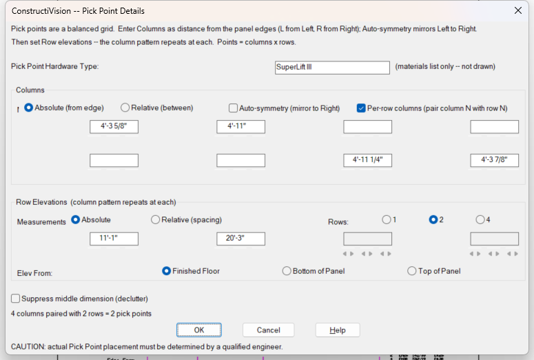
The Pick Point Details dialog — the point-grid family of dialogs. Brace Point Details follows the same idea, one row per brace elevation with up to six columns across.
Note
This lesson also exists in the browser. Work it in ConstructiVision on the web — same steps, same values, so you can follow either and end up with the same panel.
Watch this lesson
Transcript (19 captions)
0:21 — Tutorial 9 — Brace Points & Expansion Gaps. Two brace embeds at 15'-0", 6'-0" in from each edge — then 1/2" joint gaps, so the panel casts at 25'-9" while you keep typing the plan dimensions.
0:33 — Click Brace Points on the toolbar — or check Brace Points in Main Panel Details. Either route opens the same dialog.
0:35 — Six rows, one per brace elevation, up to six columns of points each. The note at the top is the whole convention: distance to Column 1 is to the EDGE of panel; all others are between columns. Elevations are from Finished Floor unless a row's T / B toggle says otherwise.
0:52 — Enable row 1 — the fields light up. T and B stay unchecked: we enter from Finished Floor.
0:53 — Measure From L — column distances read from the left panel edge.
0:55 — Elevation 15'0 — Finished Floor to the center of the brace row: clear of the 8'-0" window heads, below the 18'-0" weld plates.
0:59 — Column 1: 6'0 — left edge to the first brace point. Typing switches Auto-place off; your entered columns are used.
1:03 — Column 2: 13'10 — Column 1 to the second point. That lands it 19'-10" from the left — exactly 6'-0" from the right edge, mirroring the first. Columns 3-6 stay 0: a zero column ends the row.
1:07 — Type B-1 — the brace anchor's part number; the Materials List counts by it. Ext stays blank — no extension needed at this height.
1:11 — Auto-symmetry could have mirrored Column 1 to the right for us, and Auto-place grids braces by panel area — this lesson types both columns so the numbers match the check exactly. Suppress middle dim and the Elev From lens stay put: Finished Floor.
1:25 — OK — each brace point draws as a circular marker, a dimension string above the panel locates the columns, an elevation marker gives the row height. And the dialog says it plainly: actual placement comes from a qualified brace engineer.
1:38 — Two brace markers at 15'-0" — 6'-0", 13'-10", 6'-0" across the top — and Brace Points now checked in the feature checklist.
1:42 — Now the expansion gaps. Edit Main Panel — back to Main Panel Details, where it all started.
1:45 — Distances Specified From: Outside Wall — your dimensions are read as the architectural call-outs, and ConstructiVision deducts the gaps when it draws. On Edge of Panel, dims are taken exactly as typed and the gap values are ignored.
1:47 — Expansion Gap Left: 1/2 — no foot mark means inches.
1:50 — Right: 1/2 — a typical panel joint gap each side. This is what makes typing plan dimensions legitimate.
1:54 — OK — the translation happens: the panel casts at 25'-9", the plan width less both gaps, and edge-referenced dimensions shift by the gap on their edge. Your entered values are untouched.
2:10 — Width 25'-9"; the Lesson 5 door jamb now dimensions 3'-11 1/2" from the cast edge. One deliberate exception: brace Column 1 stays edge-of-panel — brace layouts are measured on the cast panel.
2:27 — Check your work: type CV-CHECK-LESSON9 at the command line for a graded report card. TP08-12 is brace-ready — from blank rectangle to finished panel, one feature per lesson.
Tip
The written steps below are the authoritative version — they are kept current continuously, while videos are re-recorded in batches. Companion video versions lists which build each video was recorded against.
Recorded in the earlier lesson order
This video was recorded before the course moved to build order (2026-10-09). Its second half sets the expansion gaps, which is now step 8 of Tutorial 2; the brace-point steps are the same. Because the gaps came after the braces in that order, the video’s first brace frame shows a 25’-10” panel and the second point 6’-0” from the right edge; in build order the panel is already 25’-9” when you place the braces.
What you will build
You finish panel TP08-12 — the gable-end panel carrying the windows, door, chamfer, weld plates, ledger hardware and roof line from the previous lessons, cast at 25’-9” with its 1/2” expansion gaps. In this lesson you place a row of two brace points at 15’-0” above Finished Floor, the first 6’-0” in from the left edge and the second 13’-10” past it — clear of the window heads at 8’-0” and below the weld plates at 18’-0”.
When you finish, both brace embeds are drawn, dimensioned, and counted.
Before you start
Complete Tutorial 3: Panel Lines — this lesson picks up the project and panel TP08-12 where that lesson left them.
Have panel TP08-12 open. Any panel works — the values below are what make the result checkable.
Lesson
Open Brace Point Details. Click Brace Points on the toolbar, or check Brace Points in the Main Panel Details feature checklist — either route opens the same Brace Point Details dialog.
Read the grid. Six rows, one per brace elevation; each row holds up to six columns of points. The columns are Enable, T/B, Elevation, Measure From (L / R), Column 1 through Column 6, and a stacked Type / Ext pair. The note across the top of the dialog states the two conventions everything else follows:
Distance to Column 1 is to Edge of Panel; all others are distances between columns.
Elevations are from FF unless specified — the row’s T / B toggles switch that row’s entry to read as a distance from Top- or Bottom-of-Panel instead, matching how some lift-engineering sheets call out brace heights. Whichever way you enter it, the drawing dimensions the row from Finished Floor.
As in every lesson, a row’s fields stay greyed out until its Enable box is checked.
Enter the brace row. Check Enable on row 1, leave T and B unchecked, and type:
Elevation:
15'0— Finished Floor to the center of the brace row.Measure From: L — column distances read from the left panel edge.
Column 1:
6'0— left edge to the first brace point.Column 2:
13'10— distance from Column 1 to the second point. That lands it 19’-10” from the left edge of the cast panel; on the 25’-9” cast width that leaves 5’-11” to the right edge (see the note after step 5). Leave Columns 3–6 at0— a zero column is a blank entry and switches off the columns after it.Type:
B-1— the brace anchor’s part number or description, free text. Leave Ext (the brace extension part, needed only on tall panels) blank.
The values are typed the same way as every lesson —
13'10,13'-10", or166— and each box has the three small spinners for feet, inches, and sixteenths.Note
The Materials List counts brace points and extensions segregated by what you enter in Type and Ext. Leave Type blank and they are counted by the size required for the panel’s thickness instead.
Tip
Two shortcuts on the bottom row of the dialog can do parts of this for you. Auto-place (by panel area) estimates a brace count from the panel’s face area — two on a panel this size — and grids them clear of your openings; typing in any field switches it off and your entered columns are used instead. Auto-symmetry (mirror to Right) mirrors each row’s left-side columns to the right edge, so entering only Column 1 at
6'0produces the same balanced pair you just typed. This lesson enters both columns explicitly so your numbers match the check below exactly.Leave the remaining bottom-row settings alone. Suppress middle dim declutters a wide grid by dropping the center dimension — two points do not need it. The Elev From choice (Finished Floor / Bottom of Panel / Top of Panel) is the dialog’s display datum, defaulting to the Main Panel setting from Lesson 2 — leave it on Finished Floor.
Confirm. Click OK. The panel redraws: each brace point is drawn as a circular hatch marker at its position, a dimension string above the panel top locates the columns — edge to first column, column to column, last column to edge — and an elevation marker beside the left side of the panel gives the row’s height. The Brace Points toggle in the feature checklist is now on.
Warning
The dialog says it and so does this lesson: actual Brace Point placement must be determined by a qualified engineer. ConstructiVision draws the layout you specify and counts the parts — the brace count, capacity, and positions on a real job come from the brace engineer’s design.
Note
Brace points are measured on the cast panel. Tutorial 2 set Distances Specified From to Outside Wall, so the other edge distances on this panel are plan dimensions that ConstructiVision adjusts for the 1/2” gaps. Brace points are the one deliberate exception: the Column 1 distance is always to the edge of panel, regardless of that setting, because brace layouts are measured on the cast panel, not the plan wall line. So the first point sits 6’-0” from the cast left edge, the second 13’-10” past it, and the remaining distance to the cast right edge is 5’-11”.
Check your result
Tip
Check your work automatically. Type CV-CHECK-LESSON9 at the command line —
ConstructiVision grades your panel against this lesson’s values and prints a report card, with a
pointer back to the step for anything that doesn’t match.
The drawing should now show, matching your entries exactly:
Two circular brace-point markers at 15’-0” above Finished Floor — one 6’-0” from the cast left edge and one 19’-10” from it.
A dimension string above the panel top locating them: 6’-0” edge to first point, 13’-10” between points, and the remaining 5’-11” to the right edge — read on the cast panel edges.
An elevation marker beside the left side of the panel at the brace row’s height, and the brace points counted (as type B-1) in the Materials List.
Main Panel Details (open Edit Main Panel) with Brace Points checked in the feature checklist; Brace Point Details, reopened, holding row 1 exactly as entered.
If a value is off, reopen the dialog, correct the row, and confirm — the panel redraws from the corrected values, the same dialog → confirm → redraw loop as every lesson.
Where next
That completes the panel side of the curriculum — TP08-12 has gone from a blank rectangle to a fully detailed, brace-ready panel, one feature per lesson, in the order it is built.
Next lesson: Tutorial 11: Attach Panels — back to the site drawing from Tutorial 10: attach the finished panel set, print the site plan, and stand the panels on their walls.
Reference depth: Add pick points and brace points — pick points (the lifting side of the same point-grid family) and the full brace-point field notes.
Hand it to the engineer: Export lift-engineering data — send the panel out for crane and brace analysis.
Print it: Plot and print drawings covers the per-trade sheets — including the Pick / Brace Points layer preset on the CV → Print → Panel menu — and Print a panel book batches every panel in the project into a panel book.