Tutorial 8: Ledger & Top Plate
Bolt a mezzanine ledger and a top plate onto your panel — and watch the anchor bolts place, space, and respace themselves around every opening you have made so far.
A ledger is a section of treated lumber (or metal) running across the inside face of the panel, attached with anchor bolts cast into the wall — it is what carries floor and roof framing. A top plate (nailer strip) is the same idea placed along the top of the panel, where it normally also forms the panel’s top edge form. Both live in one dialog, one row per bar, and the cast-in anchor bolts draw automatically with each bar — unlike Lesson 7, where you positioned every embed yourself, here ConstructiVision counts and spaces the hardware for you.
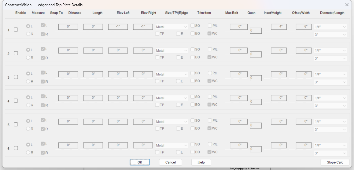
The Ledger and Top Plate Details dialog — six rows, one per bar.
Note
A browser version covers part of this lesson. Open it here — it lists exactly which steps it does not cover, so you know what to come back to AutoCAD for.
Watch this lesson
Transcript (30 captions)
0:01 — Tutorial 8 — Ledger & Top Plate. A 4 X 12 ledger bearing at 7'-6", and a 4 X 6 top plate on edge riding the roof slopes — with every anchor bolt placed, spaced, and respaced for you.
0:14 — Click Ledger / Top Plate on the toolbar — or check it in Main Panel Details. Either route opens the same dialog.
0:17 — Six rows, one per bar — a ledger, or a top plate when its TP box is checked. The columns: Enable, Measure, Snap To, Distance, Length, Elev Left / Right, Size with TP and E, Trim from, Max Bolt, Quan, Inset, Offset, and the bolt Diameter / Length lists.
0:34 — Row 1 — the ledger. Check Enable and the row lights up; an unchecked row keeps its values but stays out of the drawing.
0:35 — Snap To L — one end registers against the left edge. Distance zeroes and greys: a derived value.
0:37 — Snap To R — the other end too. The bar runs edge to edge; Length takes care of itself.
0:38 — Elev Left 7'6 — the TOP of the ledger above Finished Floor: the mezzanine bearing line.
0:42 — Elev Right 7'6 — level. Two different ends would slope the bar; Slope Calc at the bottom works one out from the plans.
0:46 — The Size list — Metal, then the nominal lumber sizes.
0:56 — 4 X 12 — drawn at its dressed 3 1/2" × 11 1/2"; the drawing tells the truth about the wood. TP and E stay clear: a ledger, laid flat.
0:57 — Trim from SO — the ledger cuts wherever it crosses your two windows. The man door needs no toggle: man doors always trim. BO, P/L, and WC stay clear.
0:58 — Max Bolt 2'8 — the maximum center-to-center spacing; the bolts come out evenly spaced in each remaining segment of the bar.
1:02 — Inset 6 — first and last bolt 6" from the bar ends. Offset stays 0: a single row on the centerline.
1:05 — The bolt itself. Diameter —
1:09 — — 3/4".
1:10 — And Length —
1:17 — — 8": through the 3 1/2" ledger with the 1" cover kept in your 7 1/4" panel. Too short or too long, and ConstructiVision warns you.
1:18 — Row 2 — the top plate. Check Enable —
1:19 — — then TP: the row is now a top plate, registered against the top of the panel, and Elev Left / Right grey out.
1:20 — Snap To L —
1:22 — — and R: the plate runs the full width, following both roof slopes up and over the peak.
1:32 — Size 4 X 6 —
1:32 — — and E: on edge, narrow side against the concrete — the usual way a top plate doubles as the top edge form. Trim from stays clear; nothing reaches the top edge.
1:34 — Max Bolt 3'0.
1:38 — Inset 6, Offset 0 — same bolt rules as the ledger.
1:45 — Diameter 3/4" —
1:50 — — Length 5 1/2".
1:51 — OK — Ledger/Top Plate switches on automatically, and the panel redraws with both bars and all their hardware. No bolt was placed by hand.
2:03 — The ledger cut around the door and windows — bolts respaced per segment, at least two in every segment — its call-out and 7'-6" elevation marker, and the 4 X 6 top plate riding both slopes over the 24'-6" peak with its own bolts.
2:08 — Check your work: type CV-CHECK-LESSON8 at the command line for a graded report card. The Materials List now counts the lumber and every anchor bolt, segregated by size.
Tip
The written steps below are the authoritative version — they are kept current continuously, while videos are re-recorded in batches. Companion video versions lists which build each video was recorded against.
Recorded in the earlier lesson order
This video was recorded before the course moved to build order (2026-10-09). The panel in it already carries the roof line from Tutorial 3, which now comes after this lesson. The top plate follows the gable top either way.
What you will build
You continue with panel TP08-12 from the previous lessons — the 25’-10” wide gable-end panel with eaves at 22’-1”, a center peak at 24’-6”, the 3070 man door, the two windows, and the weld connections from Lesson 7. In this lesson you add two bars:
A 4 X 12 ledger spanning the full panel width, top of ledger at 7’-6” above Finished Floor — the bearing line for a storage-mezzanine floor — anchored with 3/4” × 8” anchor bolts at 2’-8” on center maximum. Where the ledger crosses the door and window openings, it is trimmed out automatically and the bolts respace themselves in each remaining segment.
A 4 X 6 top plate on edge along the top of the panel — following both roof slopes up and over the peak — anchored with 3/4” × 5 1/2” anchor bolts at 3’-0” on center maximum.
When you finish, both bars are drawn with their bolts, call-outs, and elevation markers, all matching the numbers you typed.
Before you start
Complete Tutorial 7: Weld Connections — this lesson picks up the project and panel TP08-12 where that lesson left them.
Have panel TP08-12 open (use Open Drawing if it is not on screen). Any panel with an opening or two works — the values below are what make the result checkable.
Lesson
Open Ledger and Top Plate Details. Click Ledger / Top Plate on the toolbar, or check Ledger/Top Plate in the Main Panel Details feature checklist — either route opens the same Ledger and Top Plate Details dialog.
Read the grid. Six rows, one per bar — and each row is a ledger, or a top plate if its TP toggle is checked. The columns: Enable, Measure (from the Left or Right panel edge), Snap To (L / R), Distance, Length, Elev Left, Elev Right, the Size list with its TP and E toggles, the Trim from toggles (SO / BO / P/L / WC), Max Bolt, Quan, Inset, Offset, and the Diameter / Length lists for the anchor bolts. The dimension boxes carry the same three small spinners as every dialog so far — feet, inches, and sixteenths — and accept dimensions in any format you read them off the plans (
7'6,7'-6", or90).Enable row 1 — the ledger. Check Enable on row 1 and the row lights up. As in every feature dialog, an unchecked row keeps its values but stays out of the drawing.
Span the full panel with Snap To. Instead of typing a distance and length, check both Snap To boxes, L and R. Each snap registers an end of the bar against a panel edge: snapping the end on the Measure From side zeroes and greys Distance, snapping the opposite end zeroes and greys Length — so with both checked, the bar runs edge to edge and both boxes grey out as derived values. (For a partial bar you would leave the snaps clear and enter Distance — from the Measure From edge to the near end of the bar — and Length; a 0 in either box means “to the edge”.)
Set the bearing elevation. Enter Elev Left
7'6and Elev Right7'6. These are the elevation of the top of the ledger above Finished Floor, at each end of the bar — the mezzanine joists hang from that line. Entering two different values slopes the ledger; the Slope Calc button at the bottom of the dialog opens the Slope Calculator if you need to work a sloped bearing line out from the plans. Ours is level, so both ends read 7’-6”.Pick the size. In the Size list, choose 4 X 12 — the list runs from Metal through the nominal lumber sizes, 2 X 4 up to 6 X 14. Lumber draws at its actual dressed size, 1/2” under nominal, so the 4 X 12 you pick is drawn 3 1/2” × 11 1/2” — the drawing tells the truth about the wood. Leave TP and E unchecked: this row is a ledger, laid flat with its wide face against the concrete.
Choose what trims the bar. In Trim from, check SO and leave BO, P/L, and WC clear. With SO checked, the ledger is cut wherever it crosses a standard opening — your two windows. The man door needs no toggle: man doors always trim the ledger, the automatic break-around promised back in Lesson 5. Two things to know about the ones you left clear:
An unchecked trim leaves the bar whole across that feature but removes the bolts that land inside it — except at weld connections, where nothing is removed.
P/L also flips how the bolts are driven: with P/L checked the row becomes quantity-driven (Quan active); with it clear — our case — the row is spacing-driven, and Max Bolt and Inset are the active pair.
Set the anchor bolts. Enter Max Bolt
2'8— the maximum center-to-center spacing; the actual spacing tightens as needed so the bolts come out evenly spaced along each segment of the bar. Enter Inset6— the first and last bolt sit 6” from the ends of the bar (also adjusted where needed to center the array in a segment). Leave Offset at0— bolts on the bar’s centerline; an Offset ofDwould ask for a double row instead. Then pick the bolt itself from the two lists on the right: Diameter3/4, Length8. Diameters run 1/4” to 2” and lengths 3” to 24” — and ConstructiVision warns you if a bolt is too short to reach through the bar into the concrete, or too long to keep 1” of cover in your 7 1/4” panel. The 3/4” × 8” bolt passes through the 3 1/2” ledger with room to spare on both counts.Enter the top plate on row 2. Check Enable on row 2, then check TP — the row is now a top plate, and Elev Left / Elev Right grey out: a top plate registers against the top of the panel, so there is no elevation to enter. Set the rest of the row:
Snap To: check both L and R — the plate runs the full width.
Size: 4 X 6, and check E — the bar stands on edge, narrow side against the concrete, the usual way a top plate doubles as the top edge form.
Trim from: leave all four clear — nothing on this panel reaches the top edge.
Max Bolt
3'0, Inset6, Offset0, Diameter3/4, Length5 1/2.
Confirm. Click OK. The Ledger/Top Plate feature switches on automatically now that at least one row is enabled, and the panel redraws with both bars and all their hardware — no bolt was placed by hand.
Check your result
Tip
Check your work automatically. Type CV-CHECK-LESSON8 at the command line —
ConstructiVision grades your panel against this lesson’s values and prints a report card, with a
pointer back to the step for anything that doesn’t match.
The drawing should now show, matching your entries exactly:
The 4 X 12 ledger across the panel with its top at 7’-6” above Finished Floor — cut wherever it crosses an opening, leaving a bar segment at each end of the panel and one between the openings. In each segment the anchor bolts are evenly spaced within your 2’-8” maximum, respaced per segment, with at least two bolts in every segment no matter how short it is.
The ledger’s call-out above the bar: 4 X 12 Ledger with 3/4 X 8 A.B. @ 32” o.c. — your size, bolt, and spacing read back off the drawing.
An elevation marker giving the top of the ledger at 7’-6”.
The 4 X 6 top plate running edge to edge along the top of the panel — following both roof slopes up and over the 24’-6” peak, not bridging flat across — with its own bolts and the call-out 4 X 6 Top Plate on Edge - 3/4 X 5 1/2 AB @ 3’-0” o.c. Max near the peak.
The anchor bolts drawn as cast-in J-bolts reaching from each bar into the concrete, on their own hardware layer — the CV → Print → Panel → Ledgers / Top Plate preset prints exactly this trade’s sheet, which is how the framing crew will see your work.
Main Panel Details (open Edit Main Panel) with the Ledger/Top Plate toggle checked in the feature checklist.
Ledger and Top Plate Details, reopened, holding both rows exactly as entered — snaps checked, Distance and Length greyed at 0, row 2’s elevations greyed under TP.
If a value is off, reopen the dialog, correct the row, and confirm — the panel redraws from the corrected values, the same dialog → confirm → redraw loop as every lesson so far. The Materials List now counts the lumber and every anchor bolt, segregated by size — worth a look before the next lesson.
Where next
Next lesson: Tutorial 3: Panel Lines — draw the roof line across the panel face, the last of the up-face work before the brace points.
Reference depth: Add a ledger and top plate — the quick task version of this lesson, including the full field table and the trim rules for blockouts, pilasters, and weld connections; Generate a materials list and Plot and print drawings for the take-off and the per-trade sheet.