Tutorial 5: Door
Place a man door in the panel — size, position, and swing — in the room the windows left for it.
A man door is a personnel-door opening. It cuts the panel like an opening does, but it also knows which way the door opens, so the drawing carries the swing symbol a door schedule expects. In this lesson you place one real door on your panel and meet every column of the Man Door Details dialog — including the ones you leave alone today.
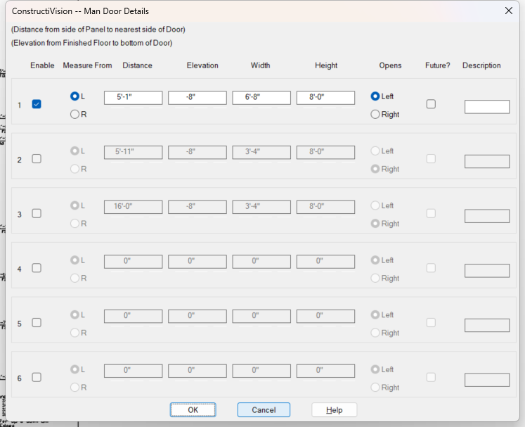
The Man Door Details dialog — six rows, one per door.
Note
This lesson also exists in the browser. Work it in ConstructiVision on the web — same steps, same values, so you can follow either and end up with the same panel.
Watch this lesson
Transcript (15 captions)
0:01 — Tutorial 5 — Door. A 3070 man door: 3'-0" × 7'-0", jamb 4'-0" from the left edge, the opening dropped 8" to the slab bottom, opening right.
0:09 — Click Man Door on the toolbar — or check Man Door in Main Panel Details. Either route opens the same dialog.
0:10 — Six rows, one per door. Distance is from the side of the panel to the nearest side of the door; Elevation is from Finished Floor to the bottom of the door.
0:21 — Enable row 1 — the rest of the row lights up.
0:22 — Measure From L. The same door could be entered from the right — R with 18'-10" places it identically.
0:24 — Distance 4'0 — the near jamb sits 4'-0" from the left edge.
0:28 — Elevation -0'-8" — the opening drops to the slab bottom, so the slab pours into it and finishes level with the apron. The panel runs 1'-6" below FF, so 10" of concrete remains under the opening.
0:32 — Width 3'0 — type it as you read it off the plans: 3'0, 3'-0", or 36.
0:36 — Height 7'8 — the opening's height from its own bottom, not a head elevation. 7'-0" of door plus the 8" it was dropped puts the head back at 7'-0" above FF.
0:40 — Opens Right — the swing symbol is what separates a man door from a plain opening.
0:41 — Future? would mark this a FUTURE OPENING and grey the swing — no door leaf yet. Leave it off; this door is real today.
0:49 — Description 101A — the architectural door mark from the plans. Optional.
0:53 — OK — the Man Door checklist toggle switches on automatically and the panel redraws with the door cut.
1:06 — The 3'-0" × 7'-0" opening, swing symbol, dimension string 4'-0" + 3'-0" + 18'-10", head marker at 7'-0" — and the Tutorial 4 chamfer already on its edges.
1:22 — Check your work: type CV-CHECK-LESSON5 at the command line for a graded report card.
Tip
The written steps below are the authoritative version — they are kept current continuously, while videos are re-recorded in batches. Companion video versions lists which build each video was recorded against.
Recorded in the earlier lesson order
This video was recorded before the course moved to build order (2026-10-09). In it the windows are not on the panel yet and the door arrives chamfered from Tutorial 4. In build order the windows come first (Tutorial 6), and the chamfer follows in Tutorial 4.
What you will build
You continue with panel TP08-12 — the gable-end panel from Tutorial 2 with its bottom 1’-6” below Finished Floor and the two windows from Tutorial 6. In this lesson you cut a 3070 man door into it: a 3’-0” × 7’-0” personnel door — the most common call-out on tilt-up plans — with its near jamb 4’-0” from the panel’s left edge, its opening dropped 8” below Finished Floor so the slab pours into it, opening to the right. When you finish, the panel shows the door cut, dimensioned from both edges, and drawn with its swing symbol. Its edges are chamfered in the next lesson, Tutorial 4.
Before you start
Complete Tutorial 6: Standard Opening — this lesson picks up panel TP08-12 where that lesson left it, with room left for this door between the left edge and the first window.
Have panel TP08-12 open (use Open Drawing if it is not on screen). Any panel works — the values below are what make the result checkable.
Lesson
Open Man Door Details. Click Man Door on the toolbar, or check Man Door in the Main Panel Details feature checklist — either route opens the same Man Door Details dialog.
Read the dialog. Six rows, one per door — a panel carries up to six man doors. Each row has an Enable toggle, a Measure From choice (L / R), four measurements — Distance, Elevation, Width, Height — an Opens choice (Left / Right), a Future? toggle, and a free-text Description. The note across the top of the dialog states the two conventions everything else follows: Distance is from the side of the panel to the nearest side of the door, and Elevation is from Finished Floor to the bottom of the door.
Enable row 1. Check Enable on row 1 — the rest of the row lights up. (An unchecked row keeps its values but is left out of the drawing, the same convention as every feature dialog so far.)
Position the door. With Measure From on L, enter Distance
4'0— the door jamb nearest the left edge sits 4’-0” from it. Measure From is the edge the distance is taken from, so the same door could equally be entered from the right: R with a distance of 18’-10”. Use whichever edge the plans dimension from — either entry places the same door, and the drawing comes out the same.Drop the opening to the slab bottom. Enter Elevation
-8— a negative elevation, 8” below Finished Floor.This is the step most people get wrong, and it is worth understanding rather than copying. The door leaf will sit on the finished floor, so it is tempting to enter
0. But the opening cast into the panel is not the door — it has to run down to the bottom of the slab, so that when the interior slab and the apron are poured, concrete flows into the opening and finishes level right through the doorway. Stop the opening at FF and you cast a panel with an 8” lip across the threshold that nobody can pour out — and the panel is wrong in a way nobody notices until it is standing.8” is the default slab thickness ConstructiVision assumes for the SB (slab bottom) elevation marker; on a job with a different slab, use that thickness instead. Remember from Tutorial 2 that this panel runs 1’-6” below FF, so the opening still stops short of the panel’s bottom edge — 10” of concrete remains below it.
Size the door. Enter Width
3'0and Height7'8. Width is the 3070 door’s 3’-0”. Height is the opening’s overall height measured up from its own bottom, not a head elevation — and because you just dropped the bottom 8”, the opening is 8” taller than the door: 7’-0” of door plus 8” of slab pocket is 7’-8”, which puts the head back at exactly 7’-0” above Finished Floor where the plans call it. As in every dialog, type the value in whatever format you read it off the plans (3'0,3'-0", or36), or rough it in with the small sliders under each box — split into feet, inches, and fractions of an inch — and let the box show the exact result.Choose the swing. Under Opens, pick Right. This is what separates a man door from a plain opening: the drawing includes the door-swing symbol so the panel sheet agrees with the door schedule.
Look at Future? — then leave it off. Check Future? on row 1 and watch the Opens choice grey out: a future opening has no door leaf yet, so there is no swing to draw. Marking a door future notes it as FUTURE OPENING on the drawing instead of a finished door. Uncheck it — this door is real today.
Describe the door (optional). In Description, enter the architectural door mark from the plans — say
101A— or a note like Hinges Up. Leave it empty if the plans give you nothing to carry.Confirm. Click OK. The Man Door feature switches on automatically — the checklist toggle in Main Panel Details always reflects whether the panel really carries at least one enabled door — and the panel redraws with the door cut.
Notice that nothing about trim was entered in this dialog. The chamfer you set in Tutorial 4 trims every opening edge on the panel, this door included, and later features that cross the door trim themselves around it the same way — when you add a ledger in Tutorial 8, it breaks around this opening automatically.
Check your result
Tip
Check your work automatically. Type CV-CHECK-LESSON5 at the command line —
ConstructiVision grades your panel against this lesson’s values and prints a report card, with a
pointer back to the step for anything that doesn’t match.
The drawing should now show, matching your entries exactly:
A 3’-0” wide × 7’-8” tall rectangular opening cut through the panel, its left jamb entered 4’-0” from the panel’s left edge and its bottom 8” below Finished Floor at the slab bottom — with 10” of concrete remaining between the opening and the bottom of the panel.
The door-swing symbol drawn in the opening, opening to the right.
The door tied into the horizontal dimension string: 3’-11 1/2” from the cast left edge to the near jamb, the 3’-0” door width, and 18’-9 1/2” from the far jamb to the cast right edge — the three add up to the 25’-9” cast width. These are the 4’-0” and 18’-10” plan distances, less the 1/2” gap on each edge from Tutorial 2.
An elevation marker at the panel edge for the door’s head (7’-0” above FF) — the 8” you added to the height is cancelled by the 8” you dropped the bottom, so the head lands exactly where the plans call it.
The opening’s bottom now lands on the SB (slab bottom) line at -0’-8” that this panel already carries — the drawing shows the doorway and the slab agreeing on one level, which is the whole point of the drop. The Finished Floor line from Tutorial 2 stays where it is.
Everything from the earlier lessons untouched: the gable outline and the two windows from Tutorial 6 are exactly as you left them.
If a value came out wrong, reopen Man Door Details, correct the row, and confirm — the panel redraws from the corrected values, the same dialog → confirm → redraw loop as every lesson so far.
Where next
Next lesson: Tutorial 4: Chamfer — bevel the panel edges and, in the same dialog, every opening edge: the door and both windows.
Reference depth: Add a man door — the quick task-reference for placing doors, with Add a standard opening and Add an overhead / dock door covering the other opening types.